
Representative point

Archived Content
Information identified as archived is provided for reference, research or recordkeeping purposes. It is not subject to the Government of Canada Web Standards and has not been altered or updated since it was archived. Please "contact us" to request a format other than those available.
Detailed definition
Censuses
Remarks
Changes prior to the current census
Detailed definition
A representative point is a coordinate point that represents a line or a polygon. The point is centrally located along the line, and centrally located or population weighted in the polygon.
Representative points are generated for block-faces, as well as for selected geographic areas – province/territory (PR), federal electoral district (FED), economic region (ER), census division (CD), census metropolitan area/census agglomeration (CMA/CA), census subdivision (CSD), population centre (POPCTR), designated place (DPL), census tract (CT), dissemination area (DA) and dissemination block (DB).
Households, postal codesOM and place of work data are linked to block-face representative points (coordinates) when the street and address information is available; otherwise, they are linked to dissemination block (DB) representative points. In some cases, postal codes and place of work data are linked to dissemination area (DA) representative points when they cannot be linked to DBs. As well, place of work data are linked to census subdivision (CSD) representative points when the data cannot be linked to DAs.
Censuses
2011, 2006, 2001, 1996, 1991, 1986, 1981, 1976, 1971
Remarks
Representative points are located by the following methods:
1. Block-face representative points
The block-face representative points are generated using the ArcGIS® software (version 9.3.1) in conjunction with the Spatial Data Infrastructure, including selected water polygons. The points are initially calculated and stored based on the Lambert conformal conic projection; they are also transformed to latitude/longitude coordinates.
The block-face representative points are computed along addressable and non-addressable streets, midway (or approximately midway) between two consecutive features intersecting a street. The intersecting features can be other streets or boundaries of standard geographic areas.
The points are set back a perpendicular distance of 10, 5, 1 or 0.5 metres from the street centre line to ensure that all points have unique coordinates, and are located in the correct block and on the correct side of the street.
Some block-face representative points may fall in water bodies if the points are adjacent to bridges or causeways.
Some geometry shifts and realignments may cause 2011 representative points for block-faces to be different from 2006.
Figure 15
Example of block-face and dissemination block representative points
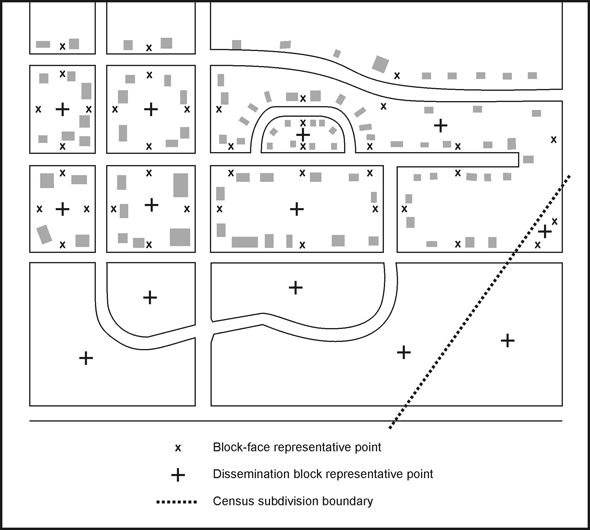
Source: Statistics Canada, 2011 Census of Population.
2. Geographic area representative points
The representative points for standard geographic areas are generated using ArcGIS® software (version 9.3.1) in conjunction with their respective digital boundary file (DBF). The most detailed hydrography is used to ensure that representative points do not fall in water where possible. The points are initially calculated and stored based on the Lambert conformal conic projection; they are also transformed to latitude/longitude coordinates.
Representative points for 2011 are generated for the dissemination block (DB) as label points to ensure they do not fall in water. The geographic area representative points are initially derived as centroids, which may fall in water. To ensure geographic area representative points do not fall in water, except in cases where entire polygons are in water, the DB representative point nearest to the geographic area centroid is selected as the new representative point for the geographic area.
A. Unweighted representative points
The representative points for all geographic areas excluding the dissemination area are unweighted. The points are generated using the ArcGIS® software. The software locates the point as nearest to the geographical centre of the polygon as possible, ensuring the point falls on land areas whenever possible. Topology checks are applied to ensure that the points fall within the appropriate geographic area. Since some dissemination blocks and designated places are located in water only, their representative points will fall in water. Where the geographic area is in multiple parts, the point is located in the portion having the largest area.
Figure 15 shows an example of dissemination block representative points.
B. Weighted representative points
Mean centre weighted by population
The representative points for dissemination areas (DAs) are weighted using the population mean centre. Formula 1 depicts the mathematical methods for calculating the weighted mean centre representative points. One of two pairs of equations is used, depending on the population of the DA. The first pair of equations is used when the DA has a population greater than zero. The second equation is used when the DA has a population equal to zero.
In the first pair of equations, the x-coordinate is calculated by first multiplying the population of each dissemination block (DB) in the DA by the x-coordinate (easting) of its representative point. The products are summed over all DBs in the DA, and the result is then divided by the total population of the DA. The y-coordinate (northing) of the DA is calculated by applying the same methodology, only using the y-coordinate information for the component DBs.
The second pair of equations is used when the DA has zero population. For this, the x-coordinate (easting) is calculated by summing the x-coordinate of the representative points of all DBs in the DA. This sum is then divided by the number of DBs in the DA. The y-coordinate (northing) of the DA is calculated by applying the same methodology, only using the y-coordinate information for the component DBs.
Examples of calculating the mean centre representative points weighted by population using the above methods are shown immediately below the formulae.
Formula 1 Mean centre weighted by population
Source: Statistics Canada, 2011 Census of Population.
Minimum squared distance weighted by population
If any weighted representative points fall outside the dissemination area (DA) (e.g., for crescent-shaped polygons) or fall in water bodies, the points are generated using the minimum squared distance weighted by population (formula 2). The first equation is used when the DA has a population greater than zero. The second equation is used when the DA has a population equal to zero.
In the first equation, the population weighted squared distance is calculated for each dissemination block (DB) and the DB with the minimum value is chosen. For each DB, the population weighted squared distance is calculated by measuring the distance between its representative point and the representative points of all other DBs. Each distance is then squared and further multiplied by the population of the other DBs. These values are then all summed to create a value for the DB in question.
In the second equation, an unweighted squared distance is calculated for each DB, and the DB with the minimum value is chosen. For each DB, the population weighted squared distance is calculated by measuring the distance between its representative point and the representative points of all other DBs. Each distance is then squared and these values are all summed to create a value for the DB in question.
Topology checks are applied to ensure that the points fall within the DA. Since some DAs are located in water only, their representative points fall in water.
Examples of calculating the minimum squared distance representative point weighted by population using the above methods are shown immediately below the formulae.
Formula 2 Minimum squared distance weighted by population
Source: Statistics Canada, 2011 Census of Population.
Refer to related definitions of block-face; census subdivision (CSD); designated place (DPL); digital boundary files (DBFs); dissemination area (DA); dissemination block (DB); geocoding; postal code; population centre (POPCTR); Spatial Data Infrastructure (SDI) and the Postal Code Conversion File (PCCF), Reference Guide (Catalogue no.92-153-G).
Changes prior to the current census
Prior to 2001, enumeration area (EA) representative points were disseminated.
Prior to 1996, all representative points were called 'centroids1'.
-
Geographic area representative points
- For 2006, the representative points for geographic areas were generated as centroids and then moved if they fell into water bodies.
- For 2001, the representative points for blocks, dissemination areas, census subdivisions and designated places could fall in water bodies. In addition, the dissemination area points were not weighted.
-
For 1996, EA representative points were disseminated in latitude/longitude coordinates and in x,y coordinates of the Lambert conformal conic projection. The representative points were created either with the Street Network File (SNF) or manually.
- Representative points located in EAs within the SNF were created using the ArcGIS® software, which located the point suitable for label or symbol placement in each polygon. Steps were taken so that the points did not fall in water bodies. If the EA was in multiple parts, the point was located, when possible, in the portion with the largest number of occupied private dwellings (based on the 1991 block-face counts). In some cases, however, the representative point was located in the EA portion having the largest land area.
- Representative points located in EAs outside SNF coverage were created by a manual procedure based on the visual inspection of building and/or street patterns on EA reference maps (some of which had topographic base map information). The representative point was located, when possible, within a predominant cluster of buildings and/or streets. If there was no predominant cluster, then the point was located between two or more clusters. In the absence of any cluster, the point was placed at the visual centre of the EA. If an EA was in multiple parts, the point was located in the portion with the largest number of dwellings. The representative point was located in the land-based portion of the EA.
- For 1991, the EA representative points within SNF coverage were created using the ArcGIS® software, which locates the point suitable for label or symbol placement in each polygon; some points were located in water bodies. In addition, for EAs in multiple parts in SNF coverage, there was no rule for selecting the EA part to which the representative point was assigned. The EA representative points were disseminated in latitude/longitude coordinates, UTM coordinates, and in x,y coordinates of the Lambert conformal conic projection.
- Prior to 1991, EA representative points within SNF coverage were computed by a different method. An algorithm selected one of the existing block-face representative points (based on their number and concentration) within an EA as the overall EA representative point. The points were calculated and disseminated in UTM coordinates.
-
Block-face representative points
- For 2001, block-face representative points were set back a distance of 10, 5 or 1 metre(s) from the street centre line. As well, points were generated when streets crossed the limits of National Topographic Database (NTDB) map tiles.
- Prior to 2001, block-face representative points were not generated when streets crossed the limits of map tiles, since map tiles were not used.
- For 1996, block-face representative points were generated within Street Network File coverage only, and the points were set back a distance of 22, 11, 5 or 1 metre(s) from the street centre line. The points were calculated in Universal Transverse Mercator (UTM) coordinates, but were disseminated in latitude/longitude coordinates.
- Prior to 1996, some block-face representative points did not have unique coordinate values, and all points were set back a perpendicular distance of 22 metres from the street centre line. The points were calculated and disseminated in UTM coordinates.
- Prior to 1991, block-faces were not created when EA boundary segments did not follow visible features.
Note:
- Date modified: